
1) Select active devices for minimum upper harmonic distortion. Although some devices have reasonably low second-harmonic distortion, the ear is not very sensitive to 2nd harmonic. It's the 3rd and higher-order harmonics that create unpleasant "electronic" colorations. D.E.L. Shorter of the BBC Research Labs and Norman Crowhurst both proposed weighting harmonics by the square or cube of the order in to reflect audibility and annoyance-factor, and it's a shame their suggestions were never carried out. To this day, it's the 2nd harmonics that dominates THD device measurements, but it's the ones that are higher than that (even though they may be 20dB lower) that we hear. That's why a THD spec, without reference to the complete spectrogram, is essentially useless, and not only that, potentially quite misleading.
In the absence of a full spectrogram, try and find a 2nd and 3rd-harmonic spec for the device you're interested in. It should be at least 20 to 30dB lower than the dominant 2nd-order distortion term. Failing that, there are some devices to avoid if you want to minimize the proportions of high-order harmonics - pentodes, beam tetrodes, transistors, MOSFETs, and IGBTs. That leaves triodes, which are not all the same.
The triodes that were the most popular in the Fifties (12AX7, 12AU7, 12AT7, and 6DJ8) were not in fact the most linear available. At the time, commercial amplifiers used at least 20dB of feedback, giving no incentive to retain big, old-fashioned octal tubes like the 6SN7 (size mattered back then). The 6SN7 came out of a prewar family of medium-mu radio tubes, starting with the single triodes 27, 37, 56, 76, 6P5, 6C5, 6J5, and then, the dual-triode 6SN7, introduced in 1940.
The 6SN7, used in millions of radios and early black-and-white TV sets, was replaced by the 12AU7 miniature tube in the early Fifties. Although the electrical characteristics appear identical in a databook (Rp=7700 ohms, mu=20), the 12AU7 has quite a bit more distortion than it's octal predecessor. In fact, the 6FQ7 miniature was introduced as a direct-replacement for the 6SN7, carrying forward the low-distortion characteristics of the 6SN7, but saw very little use in Fifties hifi equipment as a result of higher cost.
Tubes in widespread use in the Fifties have acquired a "cult" status that has nothing to do with performance, or even sonics. Believe it or not, there were better tubes both earlier and later than the "Golden Age" favorites. The 6SN7 and it's predecessors have very low distortion, almost certainly because they were designed before widespread use of feedback.
The Space Age high-transconductance tubes of the late Fifties and early Sixties never saw use in commercial hifi equipment, mostly due to cost considerations. But commercial and aerospace-grade tubes were some of the best ever made for low distortion - and favorable distribution of harmonics. The 5687, 6900, 7044, and 7119 are at the head of the line for low output impedance, wide voltage swing capability, high current, and low distortion. As for modern tubes in the same family, I've heard good things about the Sovtek 6N6 and 6H30.
Speaking of exotic, for brave souls who aren't afraid of microphonics or 50 MHz oscillations, there's the exotic (and hard-to-use) WE417A/Raytheon 5842, and the truly over-the-top WE437 or 3A/167M. (Available in modern form as the Russian 6C45pi.) Beware of large sample variations (20% or more) in this family - it's very hard to get matched pairs unless you burn them in for 100 hours and then re-test for gain. It isn't that quality is bad - the same problem is seen in genuine Western Electric 437's - it's that ultrahigh transconductance specifications requires extremely close-tolerance manufacturing. By comparison, the more moderately specified 5687, 6900, 7044, 7119, and ECC99 family is typically quite well matched, with variations of less than 5% from sample to sample.

2) Design circuits that optimize the linearity of the active device. For triodes, this means active, choke, or transformer loads. RC-coupling, although essential for the extended HF bandwidth required by feedback circuits (like the Williamson, Dynaco, or Marantz), degrades the distortion of triodes anywhere from 2 to 4 times relative to active, choke, or transformer loads.
An additional advantage of no RC coupling between the driver and output tubes is instant recovery from overload. RC coupling usually requires hundreds of milliseconds to recover the correct bias point for the output tubes. This is great for guitar amps, not so good for hifi applications, where immediate recovery is much more desirable.
3) Zero feedback in either local or global circuits. Some would say all triodes have large amounts of local feedback, but I would say, take a close look at the ratio of upper to lower harmonics. For the lower-order harmonics (2nd and 3rd), you'll see a reduction in direct proportion to the amount of feedback. But feedback generates harmonics of its own, in small magnitudes perhaps, but in greatly increased order. A classic article by Crowhurst mathematically demonstrates that a non-feedback amplifier with 9th-order harmonics acquires 81st-order harmonics when feedback is added. So feedback, while substantially reducing lower-order harmonics (the most sonically benign), also creates entirely new high-order harmonics (albeit at very low magnitudes).
So if the theory of triodes having large amounts of local feedback is correct, they'd have less distortion at low orders of harmonic distortion than pentodes, but more distortion at higher orders. This is exactly the opposite of what measurements disclose. Measurements going back as far Harry F. Olson (see below) show triodes not only have less distortion overall, but most significantly, have far less upper-harmonic distortion. In fact, vanishing amounts of upper-harmonic distortion is the distinctive hallmark of triodes, compared to all other amplifying devices.
The exceptional linearity of Class A triodes removes the need for feedback in the first place, sidestepping problems with phase margin and stability with complex and nonlinear loads ... which pretty much describes all loudspeakers. In particular, complex back-EMF currents from the drivers stop at the plates of the output tubes, instead of being mixed at the summing node with the incoming signal. This avoids load-dependent distortion terms being generated in the feedback circuit.
4) Generous driver design. Most commercial tube amps only have 1 or 2dB of headroom in the driver circuit, so the entire amp clips at once. This leads to longer recovery times and exaggerating the audibility of clipping. I prefer 3 to 6dB of headroom, so the driver can retain its (voltage) linearity even when the output stage is deep into clipping.
Perhaps more important is adequate current and low output impedance in the driver. Much of the amplifier coloration is actually in the driver, and is a result of not enough current to properly charge the grids of the output tubes. I give Arthur Loesch credit for pointing out that the "sound" of different DHT output tubes is greatly exaggerated by not having enough current in the driver. With enough current, DHT's become more transparent sounding and begin to lose the characteristic colorations they are known for. This implies that grid current is present during much of the duty cycle and is quite nonlinear. The more current available and the lower the source impedance, the less important this grid-current nonlinearity will be.
The capacitive load the output tube presents to the driver changes the load-line into an ellipse, which pushes the driver into it's nonlinear low-current region - once per cycle for a SE amp, twice per cycle for a PP amp. Pentodes have both less capacitance and half - or less - the voltage requirements of DHT's, so the driver requirements are relaxed (EL84's are particularly easy to drive, needing only 10 volts). DHT's, on the other hand, are much more severe loads, more capacitive, needing twice the voltage swing, and worst of all, exposing the driver distortion since DHT's have such low intrinsic distortion of their own. The sad fact is that many commercial DHT amplfiers, certainly all the RC-coupled designs, have more distortion in the driver than the output tube! What's the point in spending hundreds of dollars on a handmade 45, 2A3, 300B, or 845 if all you hear is the driver distortion? But that's why DHT sound quality is all over the place - the driver section isn't up to the job.
5) Absence of rectifier switching noise. The noisiest circuits of all are solid-state bridges driving large values of electrolytic capacitors. (As found in almost all transistor gear and the DC supplies for heaters and filaments.)
The commutation noise of the diodes shock-excites the RLC of the stray L in the cap bank and the stray C in the power trans secondary. The resonance of this tank circuit is typically anywhere from 4 to 20KHz and the Q's are large, anywhere from 5 to 100, depending on the DCR of the caps. This is why paralleling large values of electrolytics with "better", faster polypropylenes can frequently result in worse sound. It is also the reason power cables are audible ... they act as antennas for the small Tesla coil that most power supplies resemble. The supply radiates noise into the chassis, the power supply B+ lines, the audio circuit, and the power cable. This broadband noise can be filtered and shielded (at considerable trouble), but it is much easier to eliminate the commutation switch-noise right at the source.
Choke-fed supplies are much quieter due to the choke slowing down the rate-of-charge of the main cap bank. I use a hybrid choke-fed/pi-filter to minimize the shock-excitation of the main PS choke (this tip from the Radiotron Designers Handbook, Fourth Edition).
In terms of ragged waveforms, solid-state diodes are the worst, followed by Schottky diodes and HEXFRED's, followed by conventional tube rectifiers, followed by TV damping diodes, which are the smoothest of all in terms of the AC waveform on the power trans secondary. This, along with 2 amp peak current, is why I use them. The 30 second warmup is just a bonus.
Conclusion: This is a set of personal preferences, not the Holy Writ to Good Sound. Every designer has a set of different priorities, and this is why electronics sound different. There Is No Best. Get the idea out of your head. This is a pernicious and ugly myth propagated by greedy marketers and lazy magazine reviewers. The entire notion of an "Absolute Sound" is false. Absolute to who? To some self-appointed "expert" who knows how to write and publish a magazine? Don't be fooled.
Trust what you hear; people really do hear different things, and your perceptions are unique to you. I've been in high-end audio for thirty years now, and I've only found a handful of people who hear things the same way I do. Audio perceptions are every bit as individual as food preferences or your idea of the best lover or life companion; why should you take the guidance of a stranger you've never met? Listen for yourself, get out of the stores and hi-fi shows, and hear what's going on with the more adventurous builders. You'll be surprised.
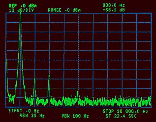
This spectrogram shows the harmonic distortion of the 1997 Amity amplifier at 1.6 watts, and was made by Matt Kamna with a Tektronix SG505 signal generator and a Hewlett-Packard 8535A spectrum analyzer. If the amplifier were distortionless, all you would see would be a single 1kHz tone extending to the top of the display, and the "grass" or noise floor at the bottom of the display.
The vertical axis is amplitude (0 to -100dB), and the horizontal axis is frequency (0 to 10kHz). The display is calibrated with horizontal lines that show 10dB intervals, and vertical lines that show 1kHz intervals. The 2nd harmonic is one interval to the right of the big signal, being at 2kHz. The smaller it is, the less the distortion. Since the top of the little bump is 7 intervals below the top of the display, that means it is 70dB below the 1kHz fundamental. -70dB corresponds to 0.03%, so the 2nd harmonic is around 0.03%.
The next little bump to the right of that is about 6.5 intervals down from the top of the display, which is 65dB below the fundamental, or about 0.05%. That's the 3rd harmonic. A little bit of 5th is peeking out from the noise, and it's around 8.2 intervals down from the top, which is -82dB down, or about 0.008%. The rest appears to be noise at the -92 to -95dB level ... this is the limit of the measuring system, not necessarily amplifier noise.
The next set of spectrograms were measured by Harry F. Olson (no relation as far as I know) and show the harmonic distortion spectra of a single-ended 6F6 pentode and a single-ended 2A3 triode. (Vertical intervals at 20 dB instead of 10 dB.)
Note that H.F. Olson's measurements are for single-ended circuits, not push-pull. If he had measured a perfectly balanced PP circuit, the even harmonics (2nd, 4th, 6th, etc.) would be completely cancelled, leaving no change in the magnitudes and proportions of the odd harmonics (3rd, 5th, 7th, etc.). Since perfectly balanced PP circuits don't exist in the real world, there is always some residue of even harmonic, which is in direct proportion to the degree of imbalance. A circuit in 10% imbalance (quite large) would have a 20dB cancellation of even harmonics, 5% imbalance (more typical) would have 26dB of even-harmonic cancellation, and 1% imbalance would have 40dB of even-harmonic cancellation.
In practice, 1% gain-matching is not going to realized under dynamic conditions. Morever, what good is accomplished by almost entirely removing even harmonics while leaving odd harmonics alone? With well-behaved triodes, the typical 5% imbalance results in even and odd harmonics conveniently having the same levels. With nonlinear triodes, though, the proportion of odd harmonics are higher, so they will dominate in a PP circuit, resulting in a more "transistor-like" sound. This is a subtle reason to seek out triodes with low proportions of 3rd-harmonic distortion when building a PP circuit (no 6DJ8's, in other words). The same qualities that make a triode desirable in a SE circuit (moderate 2nd harmonic, very low 3rd) make it even more desirable in a PP circuit.
Despite the passage of a half-century and totally different instrumentation, H.F. Olson's 1 watt SE 2A3 spectrograms are remarkably similar to the Amity PP amplifier at 1.6 watts; the 3rd harmonic is almost exactly at the same level below the fundamental, or -60dB down. Note the PP circuit gives a 26dB reduction of the 2nd harmonic compared to single-ended; this is almost exactly what would be predicted from a PP circuit with a residual 5% imbalance.
With zero feedback (local or global), a Class A PP direct-heated triode amplifier has the same (or less) distortion as a Williamson-style pentode amplifier with 20dB of feedback, which is a comment on the impressive linearity of direct-heated triodes. Not only that, the distortion spectrum is much cleaner, with almost no high-order harmonic components. This is an important reason that triodes have that hard-to-describe "direct" and "fresh" sound, while other devices sound more "canned" and "electronic" in character. The ear is not fooled by feedback; what we hear are the actual characteristics of the amplifying devices themselves.
This is why I feel that linearity right at the device level is the most important quality of an amplifier; this preference comes from a background in speaker design, where driver build quality sets the upper limit on the sonic potential of the entire system. In a similar way, the amplifying elements themselves set the upper limit on the sonics of the system.
 Revisit 300B
 Revisit 845 (IV)


